 Loading... Please wait...
GM Power Folding Mirror Gear Replacement / Repair Instructions
GruvenParts.com BRASS GM Power Folding Mirror Gear Replacement Instructions Updated 3/13/2019 – Pre-Attached Spur Gear Now Available !
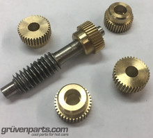
** NEW OPTION – Buy brass spur gear pre-attached to a new steel main shaft (no epoxy needed)
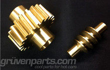
** Latest Design is uses an ALL BRASS SPUR GEAR !!! **
** If you don’t want to bother with any of this, you can now buy a rebuilt mirror drive unit and send back your core.
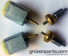
**You Must Use the GruvenParts.com replacement motors when using this brass gear. This is because the OEM motor sends current through the motor case, which isn’t a issue with the plastic spur gear. However, when using the brass spur gear, the current path could proceed to ground. Our motors do not use the motor case for the ground and therefore must be used with the brass spur gear. Please reference the motor DIY article for instructions on how to use the GruvenParts.com Motor found on the GruvenParts.com motor product page :
2007 - 2014 GM Truck Power Folding Mirror Gear & Assembly
If you are reading this DIY article, you are like many others who have a GM truck with power folding mirrors which no longer function due to a broken gear within the fold mechanism or a dead power mirror motor. This often occurs during normal operation, and especially with a light impact to the mirror housing. A broken folding mirror gear is evident when the mirror stops power folding. Sometimes you can hear the motor whirring but the mirror refuses to fold in or out. Other times, the broken gear just jams the motor and you hear nothing. You can still fold the mirror by hand. What’s happened is a gear within the assembly was made from very brittle, weak plastic. Be advised that there are MANY aftermarket replacement mirrors out on the market – READ THEIR REVIEWS. The aftermarket mirrors are very poor quality and allow the mirror itself to vibrate so badly, you cannot even see out of the mirror while driving. Not to mention the replacement mirrors will also come with the same weak spur gear that that caused this dilemma in the 1st place. The best option is to fix the OEM GM mirror with the GruvenParts.com reinforced spur gear. Also note, we now include the Hi-Torque replacement motors with this kit. Visit www.GruvenParts.com and click on the GM Trucks Section on the left banner to access the folding mirror product page.
Tools Needed :
-
Plastic pry wedge. I used a bicycle tire change lever in the pics shown below.
-
T10 torx
-
T20 torx
-
Small Phillips head screw driver
-
Small hammer and thin punch (can also use the Phillips screw driver)
-
Vice or small arbor press
-
24 hour cure 2 part metal to metal Epoxy such as JB Weld 8265 with 3,960 psi cure
strength or equivalent. DO NOT USE a 5 Minute Epoxy ! They are not as strong as the
24 hour 2 part epoxy. *Only needed if you are NOT buying the pre-attached gear option.
-
Gear grease such as Permatex White Lithium Grease P/N 80345
There is NO NEED to remove the interior door panel, or mirror base from the door. This can all be done with the mirror mounted on the door, working from outside the vehicle.
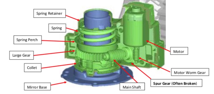
Above shows a cut away picture of the motor drive unit with the key parts you will need to reference. Please get familiar with this cut away. As you can see, the motor drive unit is very compact, and the design is actually quite nice. Unfortunately, GM has allowed the use of some cheap components within this assembly.
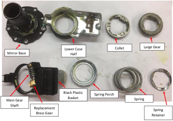
The picture below shows the components of the mirror drive unit. The unit is assembled starting with the Mirror Base in the Upper Left, and progresses to the Right as shown.
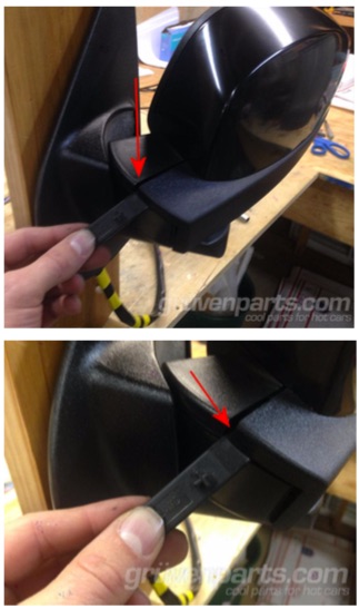
Step 1 : Plastic Shroud Removal
Fold mirror inwards and use a plastic pry tool such as plastic bicycle tire lever. Start on the inside edge as shown in the picture and gently separate the upper and lower trim shrouds as shown.
Slowly and gently work around the mirror shroud and remove both upper and lower plastic shrouds as 1 piece. You use hand force here, perhaps some gentle prying with the plastic lever.
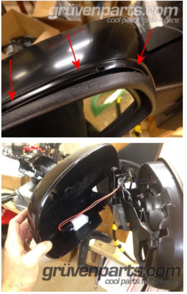
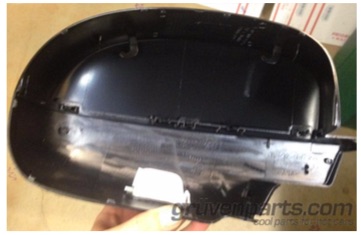
Upper/Lower Plastic Shrouds Removed
Step 2 – Disconnect Wiring from Mirror
Unplug the various connectors from their electrical connections. Mirrors may have heater wires, turn signal wires, and of course the folding mirror motor wire harness. These are all unique wire harnesses that can only be plugged in 1 way. If the mirror is a heated mirror, there will be 2 small black wires that will connect to the heater element within the mirror. These wires can be plugged into either socket on the mirror heater (you can see the 2 metal mirror heater tabs just above the white connector Im holding in the pic below).
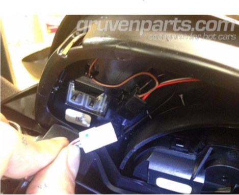
Step 3 – Remove Mirror Glass
The mirror glass is clipped into the mirror base in 4 places using small plastic tabs. You will need to disengage 1 or 2 of the plastic tabs. The mirror will move upward relative to the mirror bracket. A small screw driver can be used to push the mirror tab upward. To access the mirror tabs, it is helpful to angle the mirror facing as far down as possible. Be careful here, it’s a great idea to put some tape across the front of the mirror to prevent the mirror glass from suddenly popping out and landing face down on the driveway! See following pics.
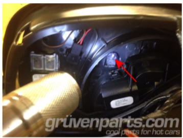
Arrow shows 1 of the mirror tabs, mirror installed looking at back side of mirror.
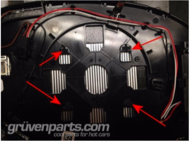
Mirror removed, see 4 tabs. Any 2 must be pushed upward to release mirror from base.
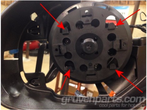
Mirror mounting base, mirror is removed in this picture. View looking aft. Arrows show the mating tabs which the mirror clips onto. When reinstalling mirror, align tabs and push mirror down onto tabs until a click is heard.
Step 4 – Removing Mirror Base
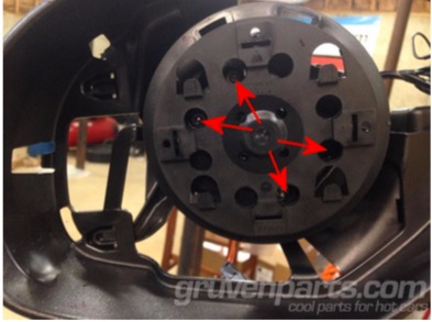
Remove (4) T10 torx screws as shown in picture. Mirror base will come off, but is still connected via the mirror adjustment wire harness. Unplug wire harness.
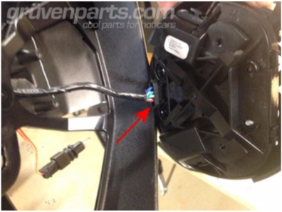
Unplug this connector
Step 5 – Mirror Frame Removal
Simply unsnap the mirror frame from the mirror assembly.
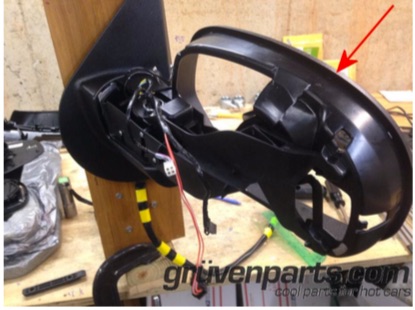
Mirror Frame is touched by arrow.
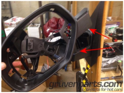
Mirror Frame unsnapped from mirror assembly. It can be set aside at this point.
Step 6 : Remove Mirror Skeleton
The mirror skeleton is held in with 3 push pins as shown in picture. Push pins can be gently tapped out to remove using a small punch or phillips head screw driver and gentle hammer taps.
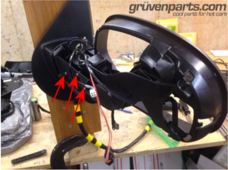
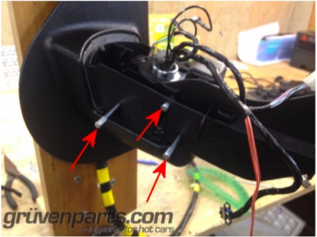
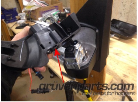
Mirror Skeleton removed, set it aside for now.
Step 7 – Remove Motor Assembly
The motor drive unit is attached to the mirror housing with (4) T20 torx screws. Remove all 4 torx screws and feed wiring harness through center of the motor drive unit. This is the housing we’re after.
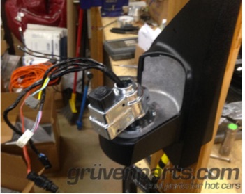
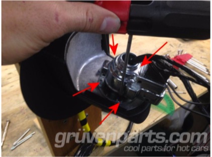
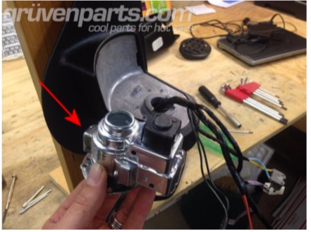
Motor Drive Unit removed.
Step 8 – Open Motor Assembly
If you bought the entire drive unit, just swap in our unit and send back your old unit. If you bought the piece parts, proceed.
Place the motor assembly in a vice with the circular base facing up as shown in the pics. You will need to pry the case halves outward a bit to disengage the snap fit. There are 4 areas where the case halves are snap fit together as shown in the pictures. You can use gentle taps from hammer to force the metal case halves outward.
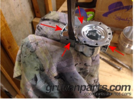
(4) Arrows show the locations of the snap fits. Flat head screw driver is inserted between the case halves, forcing outer half outward. Gently tap flat head screw driver downward to force case walls outward. Pry center portion upwards to separate.
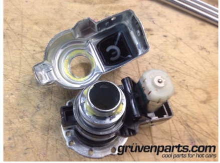
Case halves separated. Note motor on the right. Motor can be gently pulled straight up to disengage from the motor drive unit, or wait until main spring is removed and it will come up.
Step 9 – Open Motor Bracket
In order to open the motor bracket, place it in an arbor press (or vice) as shown. WEAR EYE PROTECTION !! Use a suitable socket or collar to push down on the spring retaining ring. With the spring compressed, rotate the socket or collar approximately 1/6 turn and slowly release compression on the spring. This will align the male tabs in the shaft with the female indents on the retaining ring, and allow the ring to come off the shaft. Release compression slowly, this is a pretty heavy spring. You might need to “help” the retaining collar to rotate while compressed, if its being stubborn. Just use a pair of channel locks or large pliers to grip the spring, and rotate while slightly compressed. ** It has been suggested that for “field repairs” you can use a length of 1” PVC pipe and body weight to compress and turn the spring retainer. I would wire tie the spring to the unit if you do this, to prevent It from sailing into orbit if you slip off mid turn. USE EYE PROTECTION HERE !!!
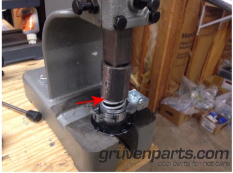
Arrow showing the retaining ring sitting just above the spring. You need to compress this and rotate the socket or collar about 1/6 turn either direction to disengage the retaining ring. Release compression slowly as the spring is heavy. You can also do this by hand with a deep well socket, by pressing down firmly on the spring then rotating. Use eye protection and be careful, the spring is heavy.
Step 10 – Remove / Replace Worm Gear
Remove retaining ring, spring, lower spring perch. Then remove the black plastic motor housing and flip over to see the discrepant worm gear that GM never wanted you to find. Gently pop this worm/spur gear out using a small flat head screw driver. Retain the brass bushings on either end.
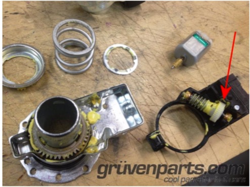
Discrepant gear shown. Note the plastic spur gear over-molded onto the metal worm gear. This is what has likely broken if you hear the motor whirring or if nothing happens when you hit the button. Most times the ger breaks apart and lodges into the unit, preventing anything from happening.
Step 11 – Prepare Worm Shaft for Installation of GruvenParts.com Reinforced Spur Gear
This is only required if you bought the loose spur gear. If you bought the pre-attached spur gear with new main shaft, skip this step! Remove the OEM spur gear, and any remnants still stuck onto worm gear shaft. It should just pull right off. You can use a box cutter or other sharp blade if needed, you won’t hurt the underlying steel worm shaft. You could also use a propane torch and simply melt the old plastic spur gear off the steel worm shaft. Usually it just crumbles right off and leaves little or no residue.
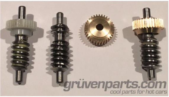
OEM main worm shaft with over-molded plastic spur gear show on the far left. OEM main worm shaft 2nd from left shown with plastic spur section removed. GruvenParts.com brass spur gear shown 2nd from right. GruvenParts brass spur gear shown installed via 24 hour JB Weld epoxy on far right.
Step 12 – Install GruvenParts.com Brass Spur Gear onto Worm Shaft
Again, skip the epoxy part if you bought the pre-attached spur gear with new main shaft. First, test fit the new gear dry. Then, apply generous coat of 2 part epoxy such as JB Weld 24 hour cure or equivalent strong 2 part metal to metal epoxy to the underlying steel worm gear teeth. Don’t use a 5 minute epoxy here, use a strong 24 hour cure 2 part epoxy such as JB Weld 8265. Make sure to fully coat the grooves where the new gear will reside. Mix epoxy per manufacturers instructions. Install GruvenParts.com brass spur gear onto worm shaft by threading it on, similar to installing a nut onto a bolt. There are no internal spirals on the GruvenParts spur gear, but a threading motion helps to move the epoxy to all the surfaces. Brass gear should be installed as far as it will go on the main shaft, about 0.250”-0.300” of shaft is protruding beyond face of gear. Ensure gear rests straight on the shaft so it spins true once cured.
The epoxy will do all the work holding the new gear onto shaft, so it doesn’t need to be tight on the shaft. Wipe off any excess epoxy and allow to fully cure per manufacturers instructions for a full 24 hours.
Once epoxy has fully cured, reinstall the main shaft worm gear with the new brass gear and motor and ensure motor gear teeth make proper contact with new brass spur gear. You may need to adjust the brass bushings that the shaft rides on to ensure the gear stays centered in the motor slot. You can reposition those brass bushings slightly to ensure the shaft doesn’t have much play. Plug in motor connection and operate motor back and forth several times to ensure everything is aligned properly before reassembling – you will need to hold the motor in place if running it without the metal cover installed.
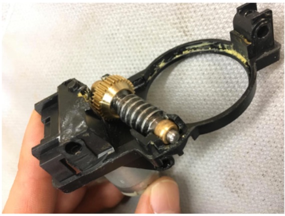
Assembly is the reverse of removal. Use Permatex White Lithium grease P/N 80345 or equivalent on all the moving parts of the mechanism when reassembling. Note the assembly order and orientation as shown on Page 3. Place the mirror base down onto the vehicle frame, it will only sit 1 way. Now, drop the lower case half onto the mirror base such that it sweeps from open to close in the proper direction. Now, drop in the collet – and NOTE : the collet will only go on 1 way. More on this below. Don’t mash it down, it will fit into the grooves in the mirror base only 1 of the 3 ways so find that correct orientation and drop it in and make sure it sits all the way flat down into the mirror base/lower case half. Do not change the orientation of these 3 parts after you align it. These mirrors can be set up to sweep on either drivers side OR passenger side! Proceed with installation of other components.
Regarding the Collet : note that it can only fit onto the Mirror Base in 1 orientation, so you will need to rotate it on the Mirror Base until you find that correct orientation. Looking DOWN on the collet from above, you will notice 3 flat landing areas. ONE of those 3 landing areas will have some sort of marking on it, like a MINUS sign, or a DOT, or an ARROW. Just 1 of the 3.
See Pic.
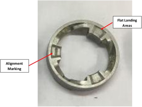
If working on the DRIVERS SIDE, this alignment mark should roughly be facing the FRONT of the vehicle.
If working on the PASSENGER SIDE, this alignment mark should roughly be facing the Passenger side window (to the left, if standing BEHIND the mirror looking forward).
Don’t get this wrong, this collet will ONLY go down properly into the base in 1 orientation, not all 3.
Also regarding the Collet – you should grind off completely the 2 protrusions on the BOTTOM side. See picture below. The reason for this is because these Tabs/Protrusions are meant to act as detents or stops for when the plastic gear breaks. When the old plastic gear breaks, It will lock the unit in the extended or retracted position, with no chance of the unit back driving due to the force of the air pushing on the mirror. These detents put a huge strain on the unit, and since the plastic gear has been changed out with a proper metal gear, these are no longer needed and therefore these tabs/protrusions can be ground flat. Use eye protection when grinding this, a Dremel tool works well here. Note your tabs might look a bit longer, that’s OK, GM made several varieties.
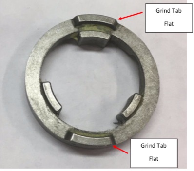
Collet Bottom Side Shown, Remove the Tabs
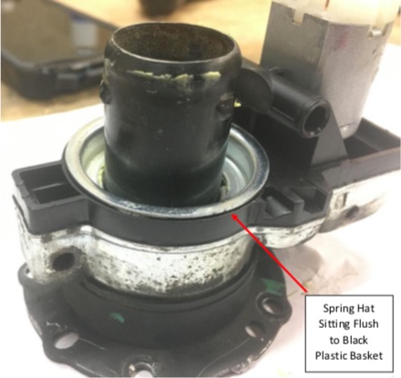
Once the case unit has been reassembled, make sure the spring hat is sitting flat on the black plastic basket as shown in the pic below. If its riding up off the basket, it means you do not have the main gear or collet situated properly. Repeat the assembly until the spring hat is sitting flat as shown below.
** TROUBLE SHOOTING / TIPS SECTION **
-
Ensure the brass gear internal bore and the main shaft worm gear are CLEAN and free of any debris before applying epoxy.
-
The new brass gear is slightly thicker in cross section. If it rubs the bottom of the black plastic housing, you can use a dremel tool or sharp knife to gently clearance the area directly under the gear. Ensure the gear can spin freely without contacting the black plastic housing.
-
When installing the brass spur gear, check to make sure its perpendicular to the main worm shaft (not crooked). Let the epoxy cure fully while the gear is held concentric to the main worm shaft. It can be a little bit off, but make sure you don’t have it too crooked to the main worm shaft. The new brass gear can wobble slightly as it turns, that’s not an issue.
-
If there is any binding in the new gear shaft, resolve the binding. Make sure the new gear shaft isn’t poking too far out on 1 side or the other past the brass bushings because it will hit the metal case that goes around it. That will jam the whole mechanism. If you need to, trim a bit of the shaft off so it doesn’t protrude past the brass bushings on either end. Use a dremel tool or similar for this, wear eye protection. It’s a hardened steel shaft, so sparks will be flying as you trim the ends off.
-
If all else fails, email us – paul@gruvenparts.com and we will help. We stand behind everything we sell. We realize this process seems difficult, due to the poor design of the OEM mechanism which we’re designing a fix for.
Most Popular
-
1
-
2
-
3
-
4
-
5

