Loading... Please wait...
Lubricating And/Or Replacing Sway Bar Bushings
Please give credit where credit is due! This DIY was completed ENTIRELY by the hardest working VW Vortex moderator on the site!! Gary Thompson, Ph.D. - vortex ID VGRT6, email addressvgrt6@yahoo.com. Please make sure to say thanks to Gary, and if you ever see him at a bar, buy em a beer. These DIY's are more complete than anything Bentley has ever written!!
REPLACING AND/OR LUBRICATING THE FRONT SWAY BAR BUSHINGS
The following outlines the procedure for replacing and/or lubricating the front sway bar bushings on a MKIV Jetta and Golf/GTI. Dry and/or worn-out sway bar bushings are often very noisy, producing a loud creaking noise when going over bumps or turning. Replacing and/or lubricating the bushings will almost always eliminate the noise.
The procedure below was based on a 99.5 Jetta GLS VR6 - it may be slightly different on later-models cars and those with the sports suspension package. Please do these procedures at your own risk and be ready to make small adjustments while doing them. Also, please be observant while removing parts so that they go back together correctly.
Please read the following carefully if you are REPLACING your front sway bar bushings with OEM (not aftermarket) bushings. This does not apply if you are only LUBRICATING your existing bushings:
It appears that VW uses two different front sway bars (at least) on the MKIV cars - one has a diameter of 21mm and the other has a diameter of 23mm. I'm not sure which cars come with which bar, but I suspect that the 21mm bar may be used on early model year cars with the regular suspension and the 23mm bar may be used on later model year cars and those with the sport/special-edition suspensions. (EDIT: Since originally posting this, it has been discovered that some/all 2000 VR6s use 23mm sway bars.) My 1999.5 Jetta VR6 came with a 21mm front sway bar. The original bushings for this sway bar (# 1J0-411-314-C) have been replaced with an updated part (# 1J0-411-314-R). Due to the slightly different shape of the new bushings, the original brackets that secure the bushings to the subframe (# 1J0-411-336-C) have also been updated with new brackets (# 1J0-411-336-D). The 23mm front sway bar uses bushings with a slightly larger diameter hole (original version - # 1J0-411-314-G, updated version - # 1J0-411-314-T) and the same 'new' brackets as the ones used for the 21mm sway bar bushings (# 1J0-411-336-D). Prior to purchasing any new bushings, I recommend that you either (1) measure the diameter of your front sway bar or (2) remove one of your existing bushings and look at the part number. If the part number for your bushings ends in 'C', purchase 'R' bushings as replacements. If the part number for your bushings ends in 'G', purchase 'T' bushings as replacements. If the part number for your bushings ends in either 'R' or 'T', purchase the same bushings as replacements. Finally, verify the part #s with your parts supplier before ordering any parts. I am not responsible if you purchase the wrong parts for your particular car.
I purchased the replacement OEM bushings and brackets from http://www.1stvwparts.com. The bushings (both 'R' and 'T' are the same price) were $11.25 each and the brackets ('D') were $5.03 each (all prices were quoted online on 8/20/03). You need two bushings and two brackets to do a complete replacement, however, you only need to buy two new bushings if you already have the new 'D' brackets on your car.
Finally, the entire replacement job should take somewhere between 1 and 2 hours, depending on ability and experience. The first time I removed the bushings to lubricate them, it took around 2 hours. I've removed the bushings 3 or 4 times now to lube, and most recently, to replace them, and now it takes me closer to an hour.
____________________________________________________________________
STEPS:
1. The replacement / lubrication of the front sway bar bushings can be done without lowering the subframe (luckily - lowering the subframe would add significant time and cost to the procedure). The procedures below can be done with the car on the ground, on ramps or on jack stands, but is significantly easier if the car is on stands. This allows the front wheels to be turned, giving better access to the sway bar bushings. Removing the front wheels also makes the procedure significantly easier, and I recommend that you do so if the car is up on stands.
2. If you are going to perform the following procedures with the car on the ground, proceed to step 6. If you are going to use ramps, drive the car up on the ramps and proceed to step 6. If you have experience jacking your car up and placing it on stands, do this as you normally would and proceed to step 6. If not, you can consider using the method I used below.
WARNING: DO NOT ATTEMPT TO PUT YOUR CAR ON STANDS IF YOU ARE NOT COMFORTABLE DOING SO. IF NOT DONE CORRECTLY, THE CAR MAY FALL, POSSIBLY CAUSING SERIOUS INJURY OR DEATH. ONLY WORK NEAR OR UNDERNEATH A CAR THAT HAS BEEN PROPERLY SUPPORTED ... DO THE FOLLOWING PROCEDURE AT YOUR OWN RISK!!!
3. Jack the car up using the pinch rails near the edge of the underside of the car. The pinch rail is indicated by the yellow arrow in the picture below and is the place used by the stock VW jack for raising the car. Make sure that the jack cup is centered on the jack point on the rail (indicated by the small indent on the lower side valence just above the yellow arrow). It is a good idea to place a thin piece of wood or hard rubber between the jack cup and pinch rail to help distribute the load and protect the underside of the vehicle from being marred. If you look closely at the picture, you should be able to see the jack on the far side of the car underneath the pinch rail. Note the 6" x 6" piece of plywood sitting on top of the jack cup.

4. The jackstands should be placed directly below the major frame rails of the car, indicated by the red arrow in the picture above. Make sure that the stands are placed towards the very front of the frame rails - this is where they are strongest. If you place the stands too far back from the front edge, you run the risk of crushing the frame rail. Don't get too close to the curved front edge of the rail, however, as there is a risk of the jack stand slipping and the car falling. I placed the jackstands just below the small hole in the bottom of the frame rail (see picture above for approximate location of stands relative to the front of the frame rail). This seemed to me to be the best compromise between safety and rail strength. Again, it is a good idea to place a protective barrier between the jack stand and the frame rail - I used a double-thick piece of regular cardboard.
5. Slowly lower the raised side of the car onto the jack stand. Repeat the above procedure (steps 3 and 4) on the other side of the car.
WARNING: MAKE SURE THE CAR IS WELL-SUPPORTED BY THE JACK STANDS BEFORE DOING ANY WORK NEAR OR UNDERNEATH THE CAR!!!
6. The general location of the sway bar bushings is indicated by the green arrow in the picture above. There are two bushings, one on each side of the car.
7. Disconnect the sway bar endlinks (both driver's and passenger's sides) from the front of the control arm by removing the lower 16mm bolt (indicated by the red arrow in the picture below). The endlinks are situated just on the inside of the front tires/brake assemblies and are visible/accessible from the front of the car. The disconnecting of the endlinks allows the brackets that secure the sway bar bushings to the subframe to be removed more easily - it would be extremely difficult/impossible to remove the brackets without performing this step.

8. If the car is up on stands (i.e., not on the ground or on ramps) and the front wheels are removed, turn the steering wheel all the way to one side. Perform the following steps on the same side of the car (i.e., if you turn the wheels to the right, perform the following steps to replace/lubricate the right (passenger's side) sway bar bushing and vice versa). Turning the wheels in this fashion will move the tie rod boots out from behind the bushings and provide significantly more room for doing the below procedure.
9. The sway bar bushings and retaining brackets are located just in front of the tie rod boots and are indicated by the yellow arrow in the picture below. The brackets are secured to the subframe by a single 13mm bolt on top (red arrow in picture below) and a curved tab on the bottom (can be seen in some of the pictures below).

10. Remove the 13mm bolt using a small socket wrench (the space is very tight - a large socket wrench may not fit), as shown below.

11. Once the bolt is removed, disconnect the bracket from the subframe by pivoting the top of the bracket towards the rear of the car (1) while at the same time lifting up on the sway bar (2), as shown below. It is somewhat difficult to remove the curved retaining tab on the bottom of the bracket from the subframe due to the tie rod boot being in the way. It may take a few minutes of wiggling the bracket back and forth while moving the sway bar around to get the tab out. Don't give up if it's difficult at first. It took me at least 10 minutes to get the bracket completely out the first time. Now that I've done it a few times, it takes less than 2 minutes. (This is where lowering the subframe would make the job easier, but that would create many other headaches and is not worth it).

12. Once the bracket has been completely removed, remove the bushing from the bar. The bushing is split on the front edge for easy removal.
13. The picture below shows how the sway bar bushing and retaining bracket fit together. The red arrow indicates the location of the 13mm bolt hole and the yellow arrow points to the curved tab that secures the bottom of the bracket to the subframe - now you know why the bracket is so difficult to remove! The green arrow indicates the location of the split in the bushing.

14. If you are only lubricating your existing bushings, do so now. A variety of water-proof lubricants should be good for this job, but I recommend (and have used) a multi-purpose silicone lubricant. You can buy a can of it at PepBoys or the like for around $3-4. After the bushings are lubricated, proceed to step 18 (skip steps 15-17 - I recommend that you read them though, even if they do not apply to your procedure).
15. The picture below shows the difference between my old (# 1J0-41-314-C, with 137k miles on it) and new (# 1J0-411-314-R) sway bar bushings. Note the extreme difference in the diameter of the hole in the bushing. I'm fairly certain that the difference is solely due to wear and not to a difference in design. Although it cannot be seen in the picture, the interior surface of the old bushing is extremely dry and cracked while that of the new bushing is soft and supple. No wonder the old bushings were so noisy!
Note: The white stuff on the surface of the new bushing is some type of silicone lubricant that is applied to the rubber to keep it soft, supple and noise-free. It is very fragile - do your best to keep it as intact as possible during the install.

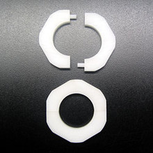
16. The picture below shows the differences between the old (# 1J0-411-336-C) and new (# 1J0-411-336-D) retaining brackets. The brackets are actually very similar, except for a bulge on the new bracket to accommodate a bulge on the side of the new bushings. I tried using the old brackets with the new bushings - it doesn't work. If you are using the 'R' or 'T' bushings, you need to use the 'D' brackets.

17. The picture below shows the new sway bar bushing and bracket together. Note how much smaller and compressed the hole in the bushing is compared to that of the old bushing. This actually makes the installation of the new bushing not just a straightforward reverse of the above steps. This will be covered in detail below.
Note: Also notice the correct orientation of the bushing in the bracket. There is a small nub on one of the front (split edge) corners of the bushing that needs to be on the bottom. Use the picture below (and others above, particularly the one of the old bushing/bracket combo) to help orient the bushing correctly.

18. Begin the reinstallation of the sway bar bushing by spraying some multi-purpose silicone lubricant on the sway bar to help the new bushing slide into place. Open up the split edge of the bushing and install it onto the bar (make sure the orientation of the bushing is correct - it's described above if you skipped steps 15-17). Slide the bushing into its approximate final location on the bar. There is a lip/stop on the sway bar just to the inside of where the bushing should sit - slide the bushing in along the bar until it makes contact with the stop. The split edge of the bushing should be towards the front of the car - it should rest against the rear edge of the subframe member.
19. The next step is definitely the most difficult of the DIY - getting the bracket into place around the bushing AND on the subframe at the same time. To do this, maneuver the bracket into position behind the bushing and try to catch the curved tab on the bottom of the bracket in the slot on the subframe while lifting the sway bar up and down (similar to the procedure used to get the bracket off, but in reverse). Once the curved tab on the bottom of the bracket has caught, push the top bracket towards the front of the car as far as possible to seat the bushing in the bracket.
20. After seating the bushing in the bracket, see if you can push the top of the bracket against the subframe member. If you are able to do this or get it within less than a cm or so, reinstall the 13mm bolt, tighten to 18 ft-lb (25 Nm) and then proceed to step 24 (skip steps 21-23). If you are not able to push the top of the bracket to within less than a cm or so of the subframe member, or if you have attempted to reinstall the bolt and the threads don't catch, continue on with step 21.
21. If you are installing new bushings or you're reinstalling bushings that are not very worn, you may encounter the situation where the top of the bracket cannot be pushed to within a cm or more of the subframe member. This is illustrated in the picture below. This is due to the fact that the hole in the new bushing is approximately 2mm smaller than the diameter of the sway bar. This cause the bushing to expand, making it difficult to seat the bushing in the bracket completely. The stock 13mm bolt that is used to secure the bracket to the subframe is a 20mm long self-tapping bolt with tapered threads toward the end. Because of the type and length of bolt used, it may not be possible to get the threads of the stock bolt to catch with such a large gap between the bracket and subframe. This is the situation that I ran into. Unfortunately, it is not possible to just use a slightly longer bolt (25mm) since the longer bolt will hit a part of the subframe before threading in completely.

22. In order to get the top of the bracket close enough to get the threads of a 20mm bolt to catch, do the following. Go to Home Depot or Lowes or any other hardware store and buy three (3) bolts - two (2) M8 x 20mm and one (1) M8 x 25mm. Thread the 25mm bolt into the hole in the subframe as far as it will go (until it hits something). This should pull the top of the bracket toward the subframe member and seat the bushing in the bracket more completely.
23. Carefully remove the 25mm bolt - try not to pull back on the top of the bracket or the bushing may squeeze out of the bracket. The gap between the top of the bracket and the subframe should be much smaller now. It should be possible to get the new (regular) 20mm bolt to thread into the hole. If it does, tighten the bolt to 18 ft-lb (25 Nm). You can also try to thread the original 20mm (self-taping) bolt into the whole, but the threads may still not catch since the end of the bolt is tapered. I ended up using the new 20mm bolt and didn't bother trying to see if the old 20mm bolt worked. The picture below shows the new sway bar bushing and bracket installed with the new 20mm bolt.

24. Turn the steering wheel all the way to the opposite side and then repeat steps 10-23 to replace and/or lubricate the bushing on the other side of the car.
25. After both front sway bar bushings have been reinstalled, reconnect the sway bar endlinks to the control arm. Tighten the bolt to 33 ft-lb (45 Nm).
26. If the car was raised during the above procedure, lower the car using the appropriate steps for the lifting method used.
27. The front sway bar bushings should now be noise free!!!
Let me know if you have any questions.
As always, do this procedure at your own risk. I am not responsible for any mistakes that you make.
Thanks to Eric (BCDS2003T) for his assistance with the procedure and the use of his parent's garage. Thanks to Shashi (DJ-SBK) for info about the bushings on his 2000 Jetta VR6.
Most Popular
-
1
-
2

-
3
-
4
-
5